

End‑to‑End IoT Product Development Playbook –Stage 2: System Architecture
Plan on Paper Before You Build
Click for previous section: Stage 1
Architecture decisions are the cheapest ones to make and the most expensive to get wrong — which is why Stage 2 happens on paper. With solid requirements in hand from Stage 1, this is where you create the high-level plan for meeting them. Think of system architecture like designing a city before building any houses or roads: you decide where the highways and bridges go before pouring concrete. In an IoT project, that means sketching the overall system on paper or a whiteboard (digital “paper” works too) before any soldering or coding happens. This stage is about big-picture thinking — making the key decisions now that will shape the design later. By the end of Stage 2, you’ll have a clear blueprint for your IoT product, and blueprints are far cheaper to change than circuit boards.
Visualize the Whole System with a Block Diagram
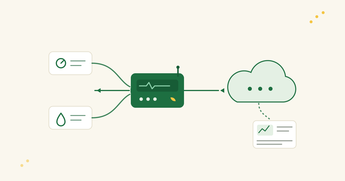
The first step is to draw a block diagram of the entire system — an architect’s floorplan for your IoT device and its ecosystem. Sketch all major components and show how they connect and communicate. A simple IoT block diagram might look like this:
- Sensor → Microcontroller (MCU/SoC) → Wireless Radio → Cloud Server → Web/Mobile App (client)
This chain is the end-to-end data path. The sensor gathers data and feeds it to the MCU. The microcontroller may do some processing, then uses a wireless radio (Wi-Fi, Bluetooth, LoRa, etc.) to send the data to a cloud server. The server stores or analyzes the data and makes it available to a user interface — a web dashboard or mobile app. With the flow laid out, everyone on the team can see all the pieces at a glance and understand how data travels through the system.
Don’t worry about art skills — simple boxes and arrows are enough. The goal is clarity. The block diagram is the big-picture map of your IoT “city”: it shows the core components and how they interact, and it prevents misunderstandings like one person assuming the device talks directly to a phone app while you intended it to go through a cloud API. When everyone sees the same map, fewer people get lost later.
Partitioning Decisions: Who Does What (and Where)?
With the system drawn, the next step is partitioning — deciding which responsibilities live where. Who does what: which tasks belong to the hardware/device, which to the firmware, and which to the cloud or server side. These decisions affect performance, cost, complexity, and security.
A few examples of partitioning decisions in an IoT system:
- Data Processing: Should raw sensor data be processed or filtered on the device, or sent raw to the cloud for heavy processing? On-device processing reduces bandwidth and cloud load, but needs a more powerful MCU and may use more battery. Sending raw data keeps the device simpler, but the backend must be robust and the data link needs enough bandwidth.
- Data Security: Will you encrypt or compress data on the device before sending, or handle that in the cloud? Encrypting on the device protects data from the moment it leaves the sensor, but demands more from the MCU. Doing it in the cloud keeps the device simpler, but data travels unsecured for a while — unacceptable in sensitive applications.
- Storage & Intelligence: If the cloud connection drops, does the device just buffer data locally — or even make local decisions? Can it operate in a “degraded” mode without the cloud? Deciding now influences whether you need extra memory or storage on the device, or extra logic for offline scenarios.
Partitioning is a balancing act: each part of the system should handle what it’s best at. A small battery-powered sensor is good at collecting data and light processing; heavy number-crunching belongs on a cloud server with power to spare. Conversely, if the application needs very fast response or must work without internet, more intelligence moves to the edge. There is no one-size-fits-all answer — the trade-offs come from your Stage 1 requirements.
Iterating on these choices is completely normal. You might start with “our device will do everything — preprocessing, encryption, decision-making” and then realize the chosen MCU can’t handle the workload, or its memory is too small. That insight might shift tasks to the cloud. Or the reverse: processing planned for the cloud moves to the device because network latency is a concern. Catching these issues on paper is far cheaper than discovering them after the code is written or a PCB has been fabricated that can’t support the firmware. Take the time to divide responsibilities well.
Technology Selection: Picking the Right Tools for Each Part
With a block diagram and partitioning in place, it’s time for technology selection: deciding the actual technologies or components for each block — or at least narrowing the options. Think of it as choosing materials for each part of a building: steel or wood frame, brick or concrete walls. In IoT terms, key considerations include:
- Sensors: Which sensor(s) do you need? This flows from the requirements. High-precision temperature readings might call for a digital temperature sensor with an I²C interface; a simple threshold detector might be fine with an analog sensor and an ADC. Consider accuracy, power consumption, cost, and ease of interfacing with the MCU.
- Microcontroller (MCU) or System-on-Chip: Choose the device’s brain. Must it be ultra-low-power (to run for years on a coin cell)? Does it need processing power or memory (for on-device processing, machine learning, or multiple sensors)? What about ecosystem — a preferred vendor, or specific development tools? You might narrow it down to: “Probably an ARM Cortex-M4 family MCU — decent CPU and floating-point for sensor calculations, with low-power modes for battery operation.”
- Connectivity (Wireless Radio): Select how the device communicates, based on range, power, and data needs. For a wearable that talks to a smartphone, Bluetooth Low Energy (BLE) fits well. For a home gadget with Wi-Fi available, Wi-Fi is convenient for cloud connectivity. For remote or wide-area devices, consider cellular IoT (LTE-M, NB-IoT) or long-range unlicensed-band radios like LoRa or Sigfox for low-bandwidth, long-range needs. Each has trade-offs: Wi-Fi and cellular give internet access but consume more power; BLE is low-power but short-range; LoRa is long-range and low-power but only for small packets.
- Power Source: How is the device powered? If it’s battery-powered, that choice shapes everything else. A coin cell demands ultra-low-power components across the board — MCU, radio, even the sensor — and power management features like sleep modes or an efficient communication protocol. Mains power gives you freedom to use power-hungry Wi-Fi or a stronger processor. Also consider battery type (rechargeable lithium-ion vs replaceable) and any charging circuitry.
- Other Components: Depending on the system, there may be more selections: display or UI hardware (LEDs, screens, buttons), actuators (motors, relays). You don’t need final part numbers for everything yet, but you should have a short list of likely candidates for each major component.
Selecting technologies at the architecture stage keeps the pieces compatible with each other and with the requirements, and it enables rough cost and feasibility checks. If you “probably” need a high-end MCU and a specific long-range radio, you can sanity-check that the combined cost fits the budget and that the parts can work together (right interfaces? driver support?). You might discover that a radio module you like only pairs with a certain MCU family or needs an external MCU — good to know now.
Also keep power and size in mind. A tiny battery-operated device (a wearable, a remote sensor) may force a system-on-chip that integrates MCU + radio to save space and power. A very cost-sensitive device might favor an all-in-one module combining sensor, MCU, and radio. This is the stage to juggle these options on paper and see which stack fits the project best.
Risk and Cost Analysis: Identify Potential Pitfalls Early
Even at this stage, a good architect starts listing risks and costs attached to the chosen design. Flagging them now beats discovering them later. Things to consider:
- Component Availability & Lead Times: Does the design rely on a component that might be hard to get? It’s common to find the “perfect” chip and then learn it has a 30-week lead time or is perpetually out of stock. A cutting-edge sensor might meet every spec but be so new that supply is limited. Identify such parts early and line up backups or sourcing plans. The same applies to single-source components — one supplier, one point of failure.
- Cost Drivers: Scan the block diagram and rough BOM for expensive items. A high-end MCU or cellular module can dominate cost; does the business case allow it? If not, reconsider now. Volume matters too: an extra $2 per device is fine for 10 prototypes but significant at 100,000 units. Adjust the architecture if needed — maybe the MCU with 1MB of flash isn’t necessary if 256KB plus a bit more cloud processing would do.
- Single Points of Failure: Think about reliability. Does the whole system break if one component fails or goes offline? If the device loses cloud connectivity, does it become useless? If so, add local backup — even just storing data to send later, or a basic “offline mode”. If the system hinges on one cloud server, consider redundancy or at least a downtime plan. Spotting weak points now lets you design mitigations: a small backup battery for the real-time clock, memory to log data when power or network is out.
- Regulatory and Compliance Issues: An often-overlooked architectural risk. A given wireless technology may require FCC/CE certification for radio emissions; certain frequency bands have legal restrictions in some countries. Healthcare or industrial use brings its own standards (medical device regulations, safety ratings). Highlight known compliance needs now so you can budget time and money for them. A cellular module may need carrier certifications, which take time; LoRa in a given region means respecting duty-cycle and power limits. Spotting these early avoids the late-stage “we can’t ship because we never got certified.”
- Integration and Complexity Risks: Flag anything technically risky — a very new IoT platform, an experimental firmware library. Acknowledge it as a risk: plan a quick prototype or research spike to test it, and keep a fallback. Early awareness of “what could go wrong” lets you design it out or prepare plan B.
A risk and cost analysis in Stage 2 means walking into development with eyes open. If the riskiest part is a custom machine learning algorithm on the device, tackle it first or monitor it closely. If the most expensive component is a certain sensor, be careful with budget elsewhere. No product is risk-free, but proactive planning is what separates calm projects from last-minute scrambles.
Documenting the Architecture Clearly
At the end of the architecture stage, document the system architecture so it’s understandable and shareable for the whole team. This document becomes the blueprint everyone refers to, so it has to live somewhere accessible — not locked in the lead engineer’s head.
Key ways to capture and communicate the architecture:
- Visual Diagrams: Show the system from different perspectives. A simple block diagram (as above) covers the high-level context of hardware and major software pieces. Some teams use formal notations like SysML or the C4 model — optional, but useful. The point is to illustrate how hardware, firmware, cloud services, and users interact. For software (device firmware and cloud), a UML component diagram — or even an annotated sketch — can show which modules run on the device versus the server. Don’t be put off by the acronyms: labeled boxes and arrows in any tool communicate well. Use whatever style your team reads best.
- Written Overview: Accompany the diagrams with a brief write-up describing each block and its role: “MCU: responsible for reading the sensor and encrypting data”; “Cloud: responsible for data storage, analytics, and providing the REST API for the app.” A few paragraphs or bullets under the diagram remove ambiguity.
- Preliminary Bill of Materials (BOM): Start a basic BOM spreadsheet listing the key components (sensor, MCU, radio module) with notes on estimated cost, vendor, and lead time or availability. Not every resistor and capacitor — those come in detailed design — just the major pieces, so unit cost and supply-chain risks are visible. If the BOM shows the wireless module at $10 and everything else at $2 combined, you immediately see where cost optimization matters. If two major parts come from the same supplier, note that too — convenient, or a risk.
- Notation & Consistency: With several people contributing, agree on naming. If the diagram says “Device CPU”, other documents shouldn’t switch between “microcontroller” and “CPU” at random — inconsistency confuses. Keep labels consistent and documentation version-controlled (a shared document or wiki page is enough). Many teams collect the diagrams and notes into a short Architecture Document that circulates for feedback and serves as a reference through development.
The goal: any team member — including a new joiner — can look at the architecture and get up to speed quickly. It also helps with non-engineering stakeholders: product managers or executives may not read your code, but they can read a high-level diagram. Good architecture documentation bridges the gap between ideas and implementation.
“Design Twice, Build Once”: Save Time with Early Planning
There’s a mantra in engineering: “design twice, build once.” Catching and fixing issues in a design on paper is far cheaper than fixing them in a built product — that is the whole philosophy of Stage 2. Moving boxes and arrows in a diagram hurts much less than re-spinning a PCB or rewriting a firmware module because the original plan turned out to be flawed.
Use this stage to get the whole team on the same page early. Architecture is multidisciplinary: hardware engineers, firmware developers, cloud/backend engineers, product managers. Everyone should have a voice in the review, so encourage discussion. A cloud engineer might say, “If the device tagged each reading with a timestamp before sending, my server side would be simpler” — a small ask, if you know it upfront. A hardware designer might note, “We use two sensors now, but a third would let us measure air quality — should we leave room for it?” Insights like these lead to small architecture tweaks, or at least provisions for future expansion, that never surface when teams work in isolation. Ironing out interface points now beats the “we can’t change this anymore” moment later.
Thoroughness here builds confidence. By the end of Stage 2 you should have a clear blueprint: a top-level design showing how you intend to meet the Stage 1 requirements. Like a building’s architectural drawing, it doesn’t pick paint colors or doorknobs yet — but the floors, doors, windows, and room layout are settled. In IoT terms: you know what the devices are, how they connect, which data flows where, and roughly which technology does the work.
With that blueprint in hand, you can move into detailed design and implementation with confidence. You’ve created a map for the IoT journey, so you’re far less likely to get lost. In Stage 3 and beyond — building hardware, writing code — you’ll refer back to this architecture constantly. And when changes come (they always do), update the architecture document so it stays a reliable reference.
In short: Stage 2, System Architecture, is where you set the project up for success. It aligns the team, exposes risks early, and provides a clear plan. You designed it — perhaps twice — so now you can build it once, and build it right. Keep the blueprint close; it will be your North Star for the rest of the journey.