

From LoRa's 6 km example to reliable FUOTA: range, airtime and Delta OTA in a mandarin orange orchard
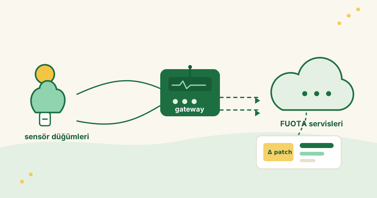
From LoRa’s 6 km example to reliable FUOTA: range, airtime and Delta OTA in a mandarin orange orchard
The range and FUOTA timings in this article are not a substitute for laboratory or field measurements. Recalculate every assumption after fixing the actual device model, antenna, regional frequency plan and channel conditions.
Summary
At first glance, the problem seems simple: can a LoRa-based sensor node send data from a mandarin orange orchard to a gateway? Once the product reaches the field, a harder question follows: how can hundreds of kilobytes of firmware be delivered reliably over the same connection?
This study starts with Semtech’s approximate 6 km example for SF9/125 kHz in its technical overview. It explains why that figure cannot be carried directly into a dense mandarin orange orchard, then examines the range–data-rate trade-off between spreading factor (SF) and bandwidth (BW). It also explains why a link budget does not mean adding the output powers of two devices: the active transmitter, the other receiver’s sensitivity, antenna gains and environmental losses must be evaluated together. The article then selects a mandarin orange orchard from several crop environments and discusses antenna height. Finally, it proposes Delta OTA instead of a full image, multi-step updates and server-side delta route selection.
The main result is simple: FUOTA success is not just a search for the longest range. Reliable downlink capacity, total airtime, duty cycle, packet loss, gateway placement, bootloader verification and update orchestration must be designed together.
1. Why Semtech’s approximate 6 km example is not a real orchard range
Semtech’s LoRa technical overview gives an example of approximately 6 km for SF9/125 kHz. The same document says that such range figures depend on terrain (Semtech, LoRa and LoRaWAN: A Technical Overview). The 6 km value is a reference for a particular modulation setting and idealised open-area conditions; it is not a guarantee of reliable two-way range in a mandarin orange orchard.
The main reasons are:
- Line-of-sight propagation in open terrain is not the same as NLOS propagation between tree rows.
- A sensor antenna close to the ground is different from the elevated gateway antenna used in a catalogue test.
- A vendor’s range depends on a particular SF/BW, packet size, antenna and power configuration.
- Usable range must include the weaker direction of the two-way link and the target packet-success rate.
- Humidity, rain, irrigation, foliage density and row orientation change over the season.
Field studies in mandarin orange orchards and other orchards have examined how leaves, branches, trunks, row geometry and antenna height affect path loss (Vougioukas et al., Influence of foliage on radio path losses for WSN planning in orchards; citrus orchard RF deployment study). Semtech’s 6 km table can therefore be a starting hypothesis for field measurements, but never the result.
The central question changes accordingly:
What link margin, packet-success rate and FUOTA airtime does Semtech’s 6 km open-area reference become inside a dense mandarin orange orchard?
2. How do SF and BW change range?
In the LoRa physical layer, spreading factor determines how widely data is spread across chirp symbols. Semtech’s overview explains that, across SF7–SF12, a higher SF improves receiver sensitivity while reducing bit rate and data-transfer speed (Semtech, LoRa and LoRaWAN: A Technical Overview).
The relationship can be summarised as follows:
| Setting trend | Range/link margin | PHY bit rate | Airtime and FUOTA effect |
|---|---|---|---|
| Lower SF | Lower | Higher | Shorter transfer |
| Higher SF | Higher | Lower | Longer transfer |
| Lower BW | Usually better sensitivity | Lower | Longer airtime |
| Higher BW | Usually lower sensitivity/margin | Higher | Shorter airtime |
Numeric SF/BW–range table for a mandarin orange orchard
The following table is an engineering planning estimate for an approximately 2.5–4 m high citrus orchard with dense, irrigated, year-round foliage. Cells use the format range (m) / gross PHY bit rate (kbit/s); for reliable design, use the lower bound of each range. The calculation scenario assumes E22-900M22S/SX1262, 868 MHz, CR 4/5, 0 dBi antenna gain, 2 dB cable/connector loss, an additional 10 dB fading/safety margin, and an antenna that is not buried (E22-900M22S manufacturer information).
| SF | BW 125 kHz: m / kbit/s | BW 250 kHz: m / kbit/s | BW 500 kHz: m / kbit/s |
|---|---|---|---|
| SF5 | 30–50 / 15.625 | 20–40 / 31.250 | 15–30 / 62.500 |
| SF6 | 35–60 / 9.375 | 25–50 / 18.750 | 20–35 / 37.500 |
| SF7 | 40–75 / 5.469 | 35–60 / 10.938 | 25–45 / 21.875 |
| SF8 | 50–90 / 3.125 | 40–70 / 6.250 | 30–55 / 12.500 |
| SF9 | 60–110 / 1.758 | 50–85 / 3.516 | 35–65 / 7.031 |
| SF10 | 75–130 / 0.977 | 60–110 / 1.953 | 40–75 / 3.906 |
| SF11 | 90–160 / 0.537 | 70–130 / 1.074 | 50–90 / 2.148 |
| SF12 | 110–200 / 0.293 | 85–160 / 0.586 | 60–110 / 1.172 |
PHY bit rate comes from R_b = SF × (BW / 2^SF) × 4/5 and is not the application’s actual throughput. LoRaWAN headers, duty cycle, waiting time, retries, fragmentation metadata and packet loss reduce useful throughput further. The ranges are planning estimates based on the stated RF assumptions, not field measurements or guarantees for a mandarin orange orchard. The SF5–SF6 and BW250/BW500 columns are raw-LoRa comparisons; combinations outside standard EU868 LoRaWAN data rates must be checked against regional parameters.
LoRaWAN regional parameters define channel plans, permitted data rates, power limits and regional restrictions. An SF/BW table must therefore be checked against the regional parameters for the country and band in use (LoRa Alliance RP002 Regional Parameters; see the LoRa Alliance Technical Committee Publications for the current publication list).
Why does ADR matter?
LoRaWAN Adaptive Data Rate (ADR) allows the network server to adjust a device’s data rate and transmit power according to link quality. Semtech describes the goal as preserving the required link margin while using a higher data rate to reduce airtime and network-capacity consumption (Semtech, Understanding LoRa Adaptive Data Rate).
For FUOTA, the implication is clear: a device should move to SF12 only when it genuinely needs to. If the link is reliable at SF9 or SF8, the lower SF can shorten the update.
3. Link budget: the two device powers are not added
One important correction is that the output powers of Dragino and E22 cannot simply be added in one link calculation. Each RF direction must be calculated separately:
received power =
active transmitter output power
+ transmit antenna gain
+ receive antenna gain
− cable/connector losses
− propagation loss
− foliage, trunk, ground and other environmental losses
For E22 → Dragino, use E22’s output power and Dragino’s receiver sensitivity. For Dragino → E22, use Dragino’s output power and E22’s receiver sensitivity. Usable two-way range is determined by the weaker of these directions. Since receiver sensitivity changes with SF, BW, coding rate and measurement conditions, a single “device range” number is technically incomplete. Semtech’s LoRa technical overview explains the relationship between LoRa modulation parameters, sensitivity and bit rate.
For this article’s field calculations, do not assume a nominal dBm value until the exact Dragino and E22 models, antenna type, conducted output power and regional permissions are fixed. Vendor datasheets do not replace field measurements.
4. Why treat crop type as a separate RF problem?
The same radio setting does not produce the same result in every agricultural environment. Leaves, branches, trunks, soil moisture, row geometry and rain can affect scattering, absorption and multipath fading. Studies have examined why line of sight is often unavailable in orchards and why foliage changes path loss (Vougioukas et al., Influence of foliage on radio path losses for WSN planning in orchards).
We therefore first considered these crops as candidate scenarios:
- corn,
- sugar beet,
- tomato,
- potato,
- watermelon,
- pepper,
- dry onion,
- grape,
- apple,
- mandarin.
This is not a global production ranking. It is an engineering candidate set combining sensor needs, irrigation/EC sensitivity, economic value and RF difficulty. For each crop, we first created a range–bit-rate table for SF/BW combinations, then a FUOTA-airtime table for the same combinations. These tables are first estimates to guide a test plan, not field guarantees.
5. Why a mandarin orange orchard?
A mandarin orange orchard is a useful stress test among these candidates:
- the trees are perennial and densely foliated,
- leaves and branches can occupy the RF path for much of the year,
- nodes are often installed close to the ground or trunk,
- several tree rows may lie between gateway and node,
- propagation along a row is not the same as propagation across rows.
The existence of RF studies that consider node placement, antenna height, vegetation depth and distance together in citrus orchards shows that antenna placement cannot be explained by distance in metres alone (citrus orchard RF deployment study). Sensor-placement experiments in citrus fields have also reported different received signal levels for different antenna heights and tree cover (Deployment Strategies of Soil Monitoring WSN for Precision Agriculture Irrigation Scheduling).
The critical question is no longer “How many kilometres can LoRa reach?” It is:
Can every sensor in the mandarin orange orchard connect with enough link margin, and can that same downlink complete a long firmware transfer?
6. Antenna height: 1 metre, 5 metres and 50 centimetres
Putting the gateway at 1 metre
A mast of roughly 1 metre can leave the antenna inside the lower trunk and foliage layer. Tree rows, branches and leaves then enter the propagation path directly. Seeing the other antenna does not mean that the Fresnel zone is clear; ground reflection and tree rows can still dominate.
Putting the gateway at 5 metres
A height of roughly 5 metres can bring the gateway antenna close to, or above, many mandarin tree tops. That does not automatically create line of sight across the whole orchard, but it can reduce gateway-side blockage, ground-related loss and the effect of tree crowns on the horizontal path. Orchard measurements show that foliage effects depend on whether antennas are near the ground or near the tree canopy (orchard foliage path-loss study).
A 5-metre mast is therefore not a “range multiplier” by itself. Measure its benefit together with:
- whether the gateway is at the orchard edge, in the centre or at the end of a row,
- whether the gateway antenna faces parallel or perpendicular to the rows,
- antenna gain and vertical radiation pattern,
- coaxial cable and connector loss,
- terrain slope and ground reflections.
Putting both antennas at 50 centimetres
The attraction of a 50 cm placement is that the antenna can stay below the upper foliage and use the corridor between trunks. But “it does not hit leaves” does not mean “there is line of sight”. At this height:
- trunks and lower branches can be direct obstacles,
- ground reflection and wet-soil loss can increase,
- a cross-row link can be significantly worse than a along-row link.
The 50 cm scenario should therefore be measured on the same route as the 1 m and 5 m scenarios; it should not be treated as a theoretical range improvement. In many orchards, a sensible hypothesis is to orient the sensor antenna toward the row corridor, raise the gateway antenna above the tree tops and add a second gateway if necessary. This is a design hypothesis derived from the height and orientation dependence reported in orchard RF studies; it must be validated in the field.
7. A telemetry link is not a FUOTA link
The fact that a sensor can regularly send a small measurement packet does not mean it can download a 1 MB firmware image over the same network. Telemetry is usually a sparse uplink; FUOTA is a long, mostly downlink-heavy operation that needs lost fragments to be retransmitted.
LoRaWAN Class A devices open two short receive windows after an uplink. Class C devices keep the receiver available for longer while they are not transmitting, which makes temporary Class C operation meaningful for a large downlink transfer (LoRaWAN Specification).
FUOTA is not one “send firmware package” command. LoRa Alliance building blocks separate the responsibilities:
- TS004 Fragmented Data Block Transport: fragmenting large data and managing the fragmentation session (TS004-2.0.0).
- TS005 Remote Multicast Setup: scheduling temporary multicast and Class B/Class C distribution windows (TS005-2.0.0).
- TS006 Firmware Management Protocol: firmware and hardware version management, reboot and update-image management (TS006-1.0.0).
- TS007 Multi Package Access: reporting device packages and FPorts so multiple commands can use fewer downlinks (TS007-1.0.0).
Using these standards together requires additional development and HIL validation, independently of RF range.
8. The cost of a 1 MB full firmware image
A rough lower-bound calculation for a 1 MB full firmware image is:
number of bits to transfer / theoretical bit rateAt 1 MB and 5.47 kbit/s, PHY transfer time alone is approximately 25.5 minutes. If we apply 10% channel use as a scenario assumption, the theoretical lower bound becomes approximately 4.25 hours. This excludes LoRaWAN headers, TS004 fragment metadata, parity/redundancy, packet loss, retries and Class C session setup. Regional law and channel-use limits must be checked for the band and country (RP002 Regional Parameters).
This is why choosing FUOTA settings only for “the longest range” can be the wrong objective. The best setting minimises total airtime while preserving a reliable link margin.
9. Delta OTA: carry the difference, not the entire firmware
With Delta OTA, the server sends the difference between the base image reported by the device and the target image. The device applies the patch to reconstruct the target firmware:
base firmware on device
        +
delta patch
        ↓
target firmware
        ↓
SHA-256 and signature verification
        ↓
MCUboot test boot and health confirmation
The open-source detools project is one example of a delta approach for embedded systems: it documents streaming application of sequential patches and incremental apply in C for memory-constrained devices (detools README). In the Agronode project, the delta creation and application flow is defined with the base SHA, target SHA, image size and MCUboot layout (Agronode Delta OTA documentation, delta application code).
The project’s current measurements report sequential release deltas of approximately 15–53 KB against a full image of approximately 944 KB (project Delta OTA documentation). This measurement is specific to those releases; the same ratio should not be expected for every version pair.
Using the same rough 5.47 kbit/s PHY value:
| Data | PHY-only lower bound | 10% channel-use assumption |
|---|---|---|
| 15 KB delta | about 22 seconds | about 3.7 minutes |
| 53 KB delta | about 78 seconds | about 13 minutes |
| 1 MB full image | about 25.5 minutes | about 4.25 hours |
This is not a real FUOTA duration; it is a size comparison. Fragmentation, parity, retries and session management add time.
10. Can very old devices be updated with small Delta steps?
Yes, if a suitable delta chain exists:
1.0.0 → 1.1.0 → 1.2.0 → 1.3.0 → ... → 1.8.0Each arrow is a separate FUOTA session and a separate security gate. The server should start the next patch only after the device has:
- completed the fragment session,
- verified the base SHA,
- built the target image and verified the target SHA,
- passed the MCUboot test boot,
- confirmed the new firmware with a health check,
- reported the new version and image identity.
MCUboot’s test–confirm–revert flow can return to the previous working image on the next boot when a new image fails; this is a core bootloader pattern for reducing remote-update brick risk (MCUboot design documentation, MCUboot image signing and tooling).
The disadvantage of a multi-step chain is that session setup, airtime, energy use, reboot and failure risk repeat at every step. If each hop has an independent 98% success probability, the probability of completing ten hops without retries is approximately 0.98^10 = 81.7%. This is not a field-success prediction; it is a model showing how hop count compounds risk.
11. The right model is a delta graph, not a list of delta files
Keeping only adjacent releases is a simple model:
1.0 → 1.1 → 1.2 → 1.3 → 1.4In production, a better approach keeps full images and multiple delta types together:
1.0 ──→ 1.1 ──→ 1.2 ──→ 1.3 ──→ 1.4
 │                  │                  ▲
 └──── checkpoint ──┴── direct patch ───┘
Recommended artifact policy:
- Store a complete, signed image for every release.
- Keep sequential
N→N+1deltas as long-lived, immutable artifacts. - Generate direct deltas from base versions actually present in the field to the latest release.
- Keep bridge deltas from selected LTS/checkpoint versions to the latest release.
- Store base SHA, target SHA, board, hardware revision, variant and partition-geometry metadata with each delta.
- Never delete full images; they remain the canonical source for delta generation, forensics and recovery.
On the Agronode side, the existing artifact script demonstrates generating direct deltas from field base versions (ensure_field_deltas.py). The current backend policy looks for a direct base–target match; a graph/path planner is additionally needed to plan A→B→C automatically when A→B and B→C exist (ota_policy.py).
The server can choose a route with this cost function:
route cost =
total patch bytes
+ estimated airtime
+ per-hop session/reboot cost
+ packet-loss and failure risk
+ device energy and maintenance cost
A practical first policy is to use a direct patch when one exists and its size is reasonable. If it is too large, try a checkpoint route with at most 2–3 controlled hops. Keep the full image as a recovery, bootstrap or alternative transport path—not as an automatic “last resort” over LoRa.
12. Security gates required for Delta OTA
Delta OTA does not remove security checks; it makes the exact identity of the base image even more important.
At minimum, verify these values for every patch:
- the base firmware SHA-256 reported by the device,
- the base SHA-256 expected by the patch,
- board and hardware revision,
- partition/slot geometry,
- target firmware SHA-256,
- MCUboot signature and permitted signing key,
- compliance of the target firmware version with the downgrade policy.
MCUboot verifies image integrity and signature and can provide rollback when a test boot is not permanently confirmed (MCUboot official documentation). Delta application code must reject base and layout mismatches before creating the target image (Agronode delta application).
Very old devices also need a defined FUOTA bootstrap version. If the firmware before that version has no fragmentation client, delta-apply code or required bootloader support, the device cannot enter the delta chain directly. Bootstrap it first through BLE, Wi-Fi, cellular connectivity or a controlled full image.
13. A workable roadmap for this project
Stage 1 — Fix the RF assumptions
- Confirm the exact Dragino and E22 model numbers.
- Select the region and frequency plan.
- Measure conducted output power or verify it from the vendor datasheet.
- Record antenna gain, cable loss and polarisation.
- Measure 50 cm, 1 m and 5 m gateway scenarios on the same route in the mandarin orange orchard.
Stage 2 — Build a field connectivity map
- Record RSSI and SNR at every measurement point.
- Measure packet-success rate and direction dependence.
- Compare dry, irrigated, rainy and different foliage-density conditions.
- Measure one route along the rows and another across the rows.
- Define the minimum link margin required for FUOTA separately.
Stage 3 — Complete the LoRaWAN FUOTA transport
- Implement the TS004 fragmentation session.
- Implement the temporary Class C/multicast lifecycle with TS005.
- Connect TS006 firmware-version/reboot management and TS007 package discovery.
- Test fragment loss, retries, interruption and gateway restart.
- Do not promise end-to-end Delta FUOTA success over LoRa before this stage is complete.
Stage 4 — Add delta artifact and route management
- Store each full signed release as a canonical artifact.
- Generate adjacent deltas and direct deltas from active field bases to the latest release.
- Keep delta metadata immutable with base/target SHA and hardware identity.
- Implement direct-patch and limited multi-hop route selection on the server.
- After every hop, wait for version, SHA, boot-health and application-health signals.
Stage 5 — Define the FUOTA success metric
Success should not mean only “all packets arrived”. Report these metrics together:
- patch bytes and total airtime,
- fragment-loss rate and retry count,
- update-completion time,
- energy consumption,
- test-boot success rate,
- permanent-confirm rate,
- rollback rate,
- per-hop and total success when multiple hops are required.
Conclusion
The LoRa problem in a mandarin orange orchard is not just “How many kilometres can we reach?” SF and BW create a range-versus-bit-rate trade-off; foliage changes the theoretical link in field conditions; antenna height and row orientation affect the result; and FUOTA needs downlink capacity very different from that of small telemetry packets.
That is why Semtech’s 6 km reference and a reliable update distance in a dense orchard do not describe the same metric. The correct architecture combines a measured RF link budget, a suitable gateway height, standard TS004/TS005 FUOTA transport, MCUboot security gates and a Delta OTA artifact graph.
When Delta OTA reduces a 1 MB full image to patches around 15–53 KB, it can dramatically reduce FUOTA airtime. But the delta algorithm alone does not turn that advantage into a reliable product. The server must know the device’s exact base SHA, select a suitable direct or limited multi-hop route, verify every hop and retain the full image as a recovery source.
In short, the goal is not the longest range. It is a LoRaWAN system that can perform a measurable, repeatable and reversible firmware update in a mandarin orange orchard.
Sources
Standards and vendor technical documents
- Semtech — LoRa and LoRaWAN: A Technical Overview
- Semtech — Understanding LoRa Adaptive Data Rate
- LoRa Alliance — RP002 Regional Parameters
- LoRa Alliance — TS004 Fragmented Data Block Transport
- LoRa Alliance — TS005 Remote Multicast Setup
- LoRa Alliance — TS006 Firmware Management Protocol
- LoRa Alliance — TS007 Multi Package Access
- LoRa Alliance — LoRaWAN Specification v1.0.3
- MCUboot — official documentation
- MCUboot — boot design and test/revert flow
- detools — sequential and incremental delta patching